Explore complete IoT practical source codes, Arduino projects, sensor interfacing programs, viva questions, and step-by-step video explanations from DEEPAKRAJTech live classes.
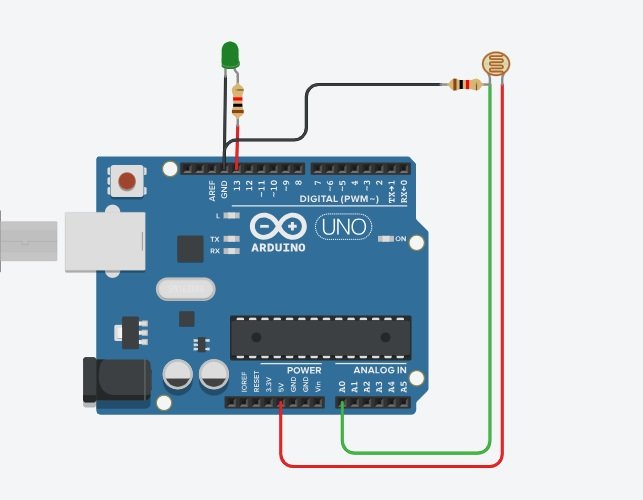
  int ldr = A0;
  int led = 13;
  int value = 0;

  void setup()
  {
    pinMode(led, OUTPUT);
    Serial.begin(9600);
  }

  void loop()
  {
    value = analogRead(ldr);

    if (value < 500)
    {
      digitalWrite(led, HIGH);
      Serial.println(value);
    }
    else
    {
      digitalWrite(led, LOW);
      Serial.println(value);
    }

    delay(500);
  }
▶️
Watch Now on YouTube
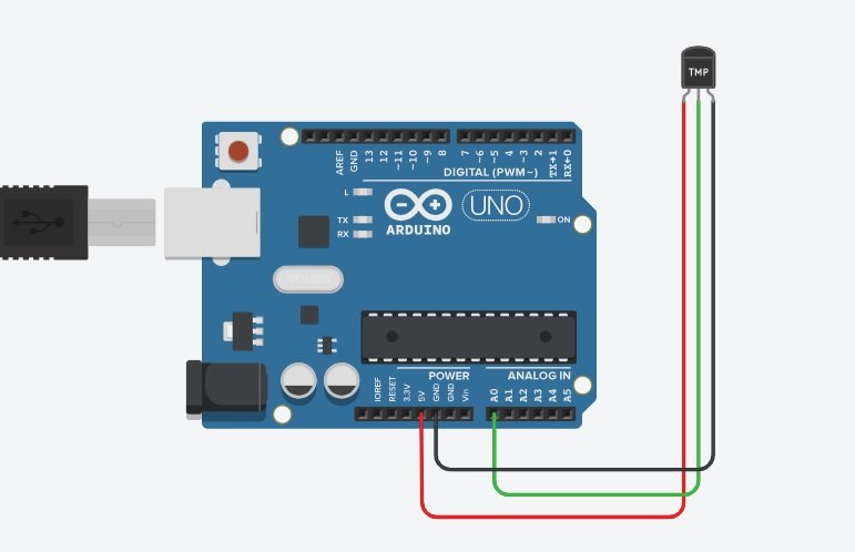
  int sensor = A0;
  int value = 0;
  float temp;

  void setup()
  {
    Serial.begin(9600);
  }

  void loop()
  {
    value = analogRead(sensor);

    temp = ((value * 5.0) / 1023.0 - 0.5) * 100;

    Serial.print("Temperature = ");
    Serial.print(temp);
    Serial.println(" C");

    delay(1000);
  }
▶️
Watch Now on YouTube
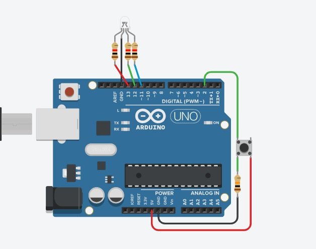
  int red = 13;
  int green = 12;
  int blue = 11;
  int button = 2;

  void setup()
  {
    pinMode(red, OUTPUT);
    pinMode(green, OUTPUT);
    pinMode(blue, OUTPUT);
    pinMode(button, INPUT);
  }

  void loop()
  {
    if (digitalRead(button) == HIGH)
    {
      digitalWrite(red, HIGH);
      delay(500);
      digitalWrite(red, LOW);

      digitalWrite(green, HIGH);
      delay(500);
      digitalWrite(green, LOW);

      digitalWrite(blue, HIGH);
      delay(500);
      digitalWrite(blue, LOW);
    }
    else
    {
      digitalWrite(red, LOW);
      digitalWrite(green, LOW);
      digitalWrite(blue, LOW);
    }
  }
▶️
Watch Now on YouTube
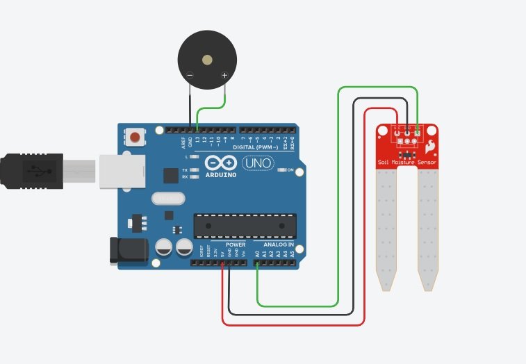
  int sensor = A0;
  int buzzer = 13;
  int value;

  void setup()
  {
    Serial.begin(9600);
    pinMode(buzzer, OUTPUT);
  }

  void loop()
  {
    value = analogRead(sensor);

    Serial.println(value);

    if (value < 300)
    {
      tone(buzzer, 750);
    }
    else
    {
      noTone(buzzer);
    }

    delay(200);
  }
▶️
Watch Now on YouTube
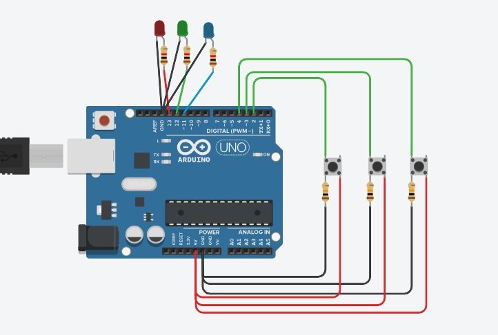
  int btn1 = 2;
  int btn2 = 3;
  int btn3 = 4;

  void setup()
  {
    pinMode(btn1, INPUT);
    pinMode(btn2, INPUT);
    pinMode(btn3, INPUT);

    pinMode(13, OUTPUT);
    pinMode(12, OUTPUT);
    pinMode(11, OUTPUT);
  }

  void loop()
  {
    if (digitalRead(btn1) == HIGH)
      digitalWrite(13, HIGH);
    else
      digitalWrite(13, LOW);

    if (digitalRead(btn2) == HIGH)
      digitalWrite(12, HIGH);
    else
      digitalWrite(12, LOW);

    if (digitalRead(btn3) == HIGH)
      digitalWrite(11, HIGH);
    else
      digitalWrite(11, LOW);

    delay(100);
  }
▶️
Watch Now on YouTube
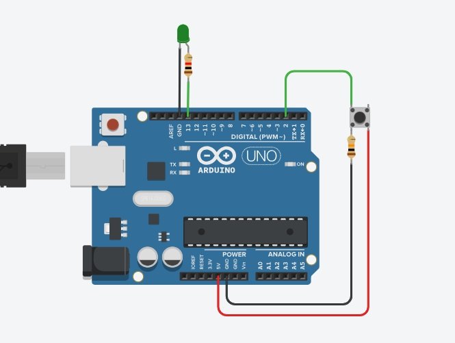
  int button = 2;
  int led = 13;

  int ledState = LOW;
  int lastButtonState = LOW;

  void setup()
  {
    pinMode(button, INPUT);
    pinMode(led, OUTPUT);
  }

  void loop()
  {
    int currentButtonState = digitalRead(button);

    if (currentButtonState == HIGH && lastButtonState == LOW)
    {
      ledState = !ledState;
      digitalWrite(led, ledState);
      delay(100);
    }

    lastButtonState = currentButtonState;
  }
▶️
Watch Now on YouTube
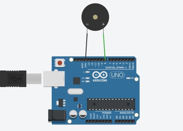
  int buzzer = 8;

  void setup()
  {
    pinMode(buzzer, OUTPUT);
  }

  void loop()
  {
    for (int i = 500; i <= 1000; i += 10)
    {
      tone(buzzer, i);
      delay(10);
    }

    for (int i = 1000; i >= 500; i -= 10)
    {
      tone(buzzer, i);
      delay(10);
    }
  }
▶️
Watch Now on YouTube
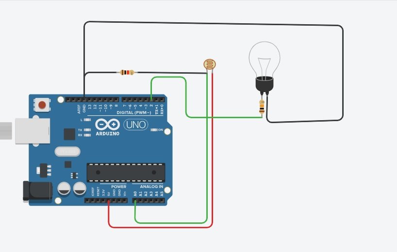
  int ldr = A0;
  int bulb = 2;

  void setup()
  {
    pinMode(bulb, OUTPUT);
    pinMode(ldr, INPUT);
  }

  void loop()
  {
    if (analogRead(ldr) > 500)
      digitalWrite(bulb, LOW);
    else
      digitalWrite(bulb, HIGH);
  }
▶️
Watch Now on YouTube
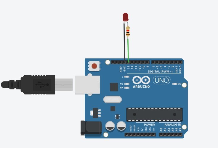
  void setup()
  {
    pinMode(13, OUTPUT);
  }

  void loop()
  {
    digitalWrite(13, HIGH);
    delay(500);

    digitalWrite(13, LOW);
    delay(500);
  }
▶️
Watch Now on YouTube
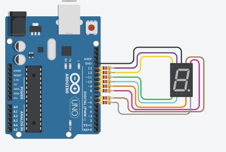
  // 7-Segment Display ke Segments ka Arduino Pins se Connection

  int a = 7;
  int b = 8;
  int c = 9;
  int d = 10;
  int e = 11;
  int f = 13;
  int g = 12;

  // 0 se 9 tak ke Numbers ki Binary Table (1 = ON, 0 = OFF)

  int n[10][7] = {
    {1, 1, 1, 1, 1, 1, 0}, // 0
    {0, 1, 1, 0, 0, 0, 0}, // 1
    {1, 1, 0, 1, 1, 0, 1}, // 2
    {1, 1, 1, 1, 0, 0, 1}, // 3
    {0, 1, 1, 0, 0, 1, 1}, // 4
    {1, 0, 1, 1, 0, 1, 1}, // 5
    {1, 0, 1, 1, 1, 1, 1}, // 6
    {1, 1, 1, 0, 0, 0, 0}, // 7
    {1, 1, 1, 1, 1, 1, 1}, // 8
    {1, 1, 1, 1, 0, 1, 1}  // 9
  };

  void setup()
  {
    // Sabhi Pins ko Output Set Karna

    pinMode(a, OUTPUT);
    pinMode(b, OUTPUT);
    pinMode(c, OUTPUT);
    pinMode(d, OUTPUT);
    pinMode(e, OUTPUT);
    pinMode(f, OUTPUT);
    pinMode(g, OUTPUT);
  }

  void loop()
  {
    // 0 se 9 tak Counting

    for (int i = 0; i < 10; i++) {
      displayNumber(i);
      delay(1000);
    }
  }

  // Display par Number Dikhane ka Function

  void displayNumber(int i)
  {
    digitalWrite(a, n[i][0]);
    digitalWrite(b, n[i][1]);
    digitalWrite(c, n[i][2]);
    digitalWrite(d, n[i][3]);
    digitalWrite(e, n[i][4]);
    digitalWrite(f, n[i][5]);
    digitalWrite(g, n[i][6]);
  }
▶️
Watch Now on YouTube
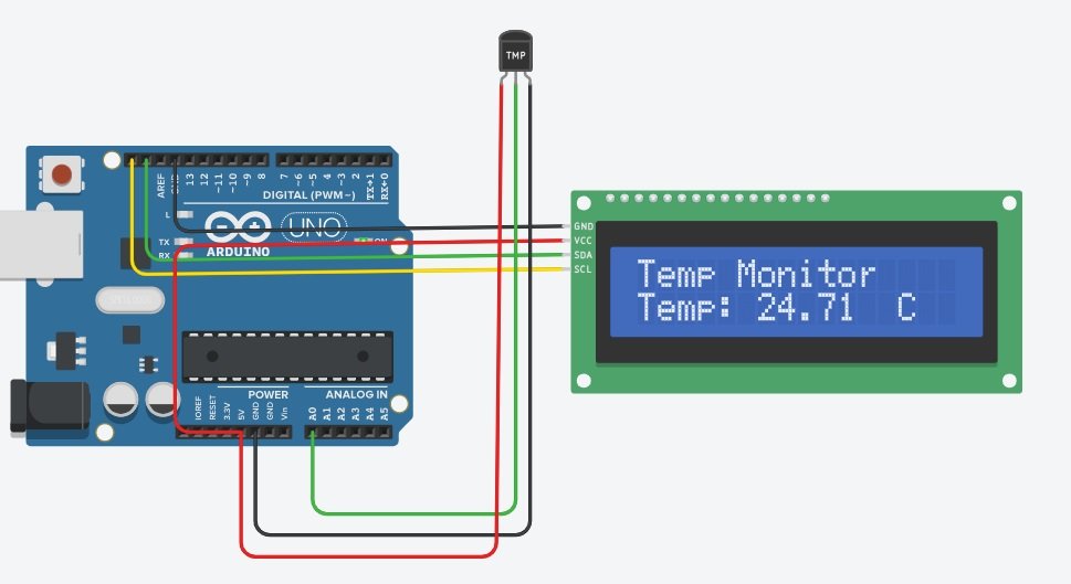
  #include <Adafruit_LiquidCrystal.h>

  Adafruit_LiquidCrystal lcd(0);

  const int sensorPin = A0;

  void setup()
  {
    lcd.begin(16, 2);
    lcd.print("Temp Monitor");
  }

  void loop()
  {
    int reading = analogRead(sensorPin);

    float voltage = reading * (5.0 / 1024.0);

    float temp = (voltage - 0.5) * 100;

    lcd.setCursor(0, 1);
    lcd.print("Temp: ");
    lcd.print(temp);
    lcd.print("  C   ");

    delay(1000);
  }
▶️
Watch Now on YouTube
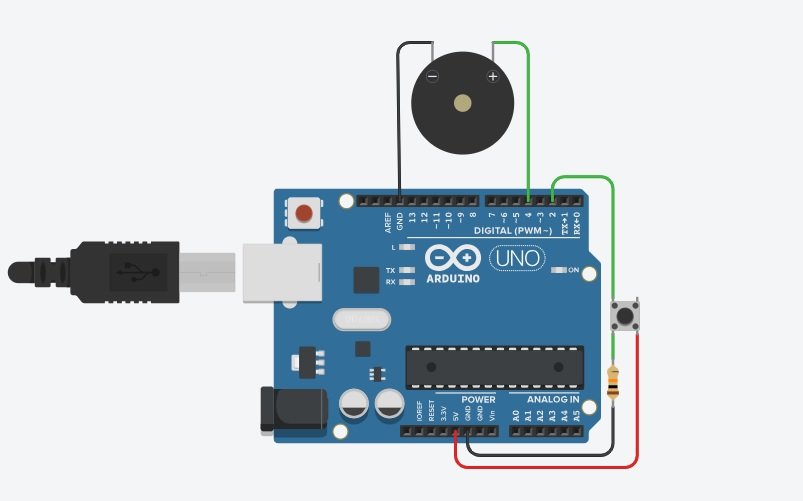
  int state = 1;

  void setup()
  {
    pinMode(2, INPUT_PULLUP);
  }

  void loop()
  {
    if (digitalRead(2) == LOW) {

      state = !state;

      if (state)
        tone(4, 700);
      else
        noTone(4);

      while (digitalRead(2) == LOW);

      delay(100);
    }
  }
▶️
Watch Now on YouTube
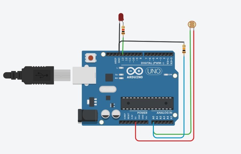
  void setup()
  {
    pinMode(13, OUTPUT);

    Serial.begin(9600);
  }

  void loop()
  {
    if (analogRead(A0) < 550) {
      digitalWrite(13, HIGH);
    }
    else {
      digitalWrite(13, LOW);
    }

    Serial.println(analogRead(A0));

    delay(100);
  }
▶️
Watch Now on YouTube
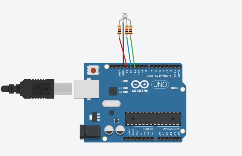
  void setup()
  {
    pinMode(13, OUTPUT);
    pinMode(12, OUTPUT);
    pinMode(11, OUTPUT);

    Serial.begin(9600);
  }

  void loop()
  {
    digitalWrite(13, HIGH);
    Serial.println("Red LED ON");
    delay(2000);
    digitalWrite(13, LOW);

    digitalWrite(12, HIGH);
    Serial.println("Blue LED ON");
    delay(2000);
    digitalWrite(12, LOW);

    digitalWrite(11, HIGH);
    Serial.println("Green LED ON");
    delay(2000);
    digitalWrite(11, LOW);
  }
▶️
Watch Now on YouTube
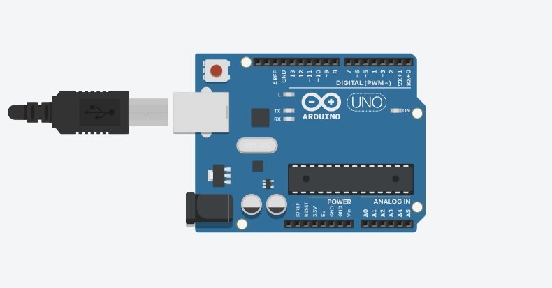
  void setup()
  {
    Serial.begin(9600);
  }

  void loop()
  {
    Serial.println("Hello, Arduino!");

    delay(1000);
  }
▶️
Watch Now on YouTube
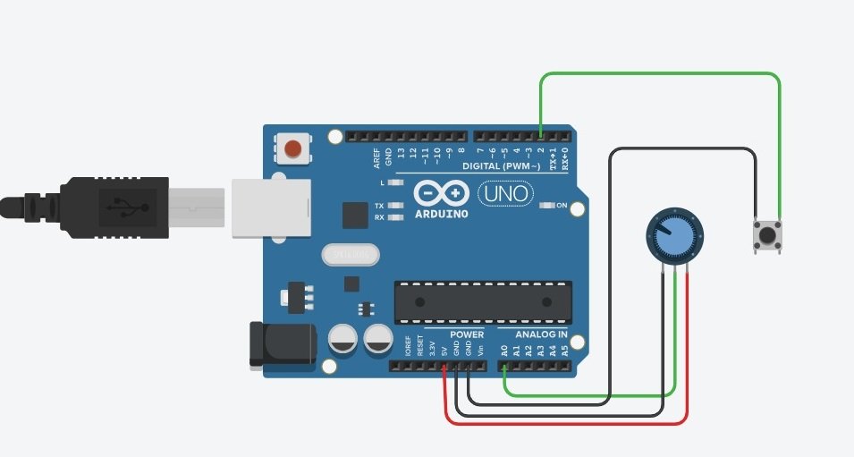
  void setup()
  {
    pinMode(2, INPUT_PULLUP);
    Serial.begin(9600);
  }

  void loop()
  {
    int analogValue = analogRead(A0);
    int buttonState = !digitalRead(2);

    Serial.print("analog = ");
    Serial.print(analogValue);

    Serial.print("    Button = ");
    Serial.println(buttonState);

    delay(1000);
  }
▶️
Watch Now on YouTube
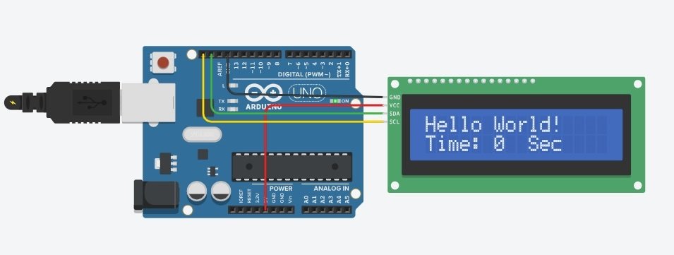
  #include <Adafruit_LiquidCrystal.h>

  Adafruit_LiquidCrystal lcd(0);

  void setup()
  {
    lcd.begin(16, 2);
    lcd.setBacklight(1);

    lcd.setCursor(0, 0);
    lcd.print("Hello World!");
  }

  void loop()
  {
    lcd.setCursor(0, 1);
    lcd.print("Time: ");
    lcd.print(millis() / 1000);
    lcd.print("  Sec  ");

    delay(1000);
  }
▶️
Watch Now on YouTube
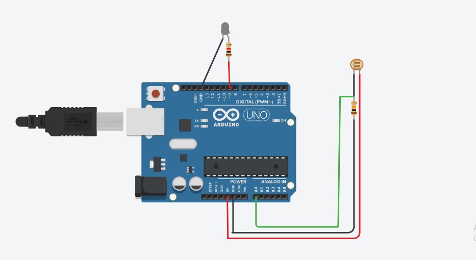
  int ldrPin = A0;
  int ledPin = 9;
  int ldrValue = 0;
  int threshold = 500;

  void setup() {
      pinMode(ledPin, OUTPUT);
      Serial.begin(9600);
  }

  void loop() {
      ldrValue = analogRead(ldrPin);
      Serial.println(ldrValue);

    if (ldrValue < threshold) {
          digitalWrite(ledPin, HIGH);
    } else {
          digitalWrite(ledPin, LOW);
    }

      delay(100);
  }
▶️
Watch Now on YouTube
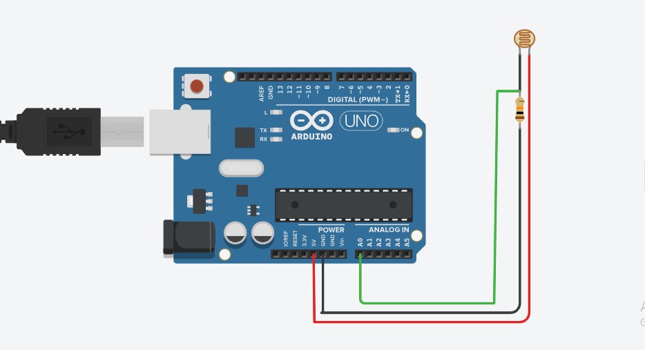
  // Reads LDR values and prints them to Serial Monitor

  int ldrPin = A0;   // LDR connected to analog pin A0
  int ldrValue = 0;  // Variable to store LDR value

  void setup() {
      Serial.begin(9600);  // Start Serial communication
  }

  void loop() {
      ldrValue = analogRead(ldrPin);
      Serial.print("LDR Value: ");
      Serial.println(ldrValue);

      delay(1000); // Wait for 1 seconds
  }
▶️
Watch Now on YouTube
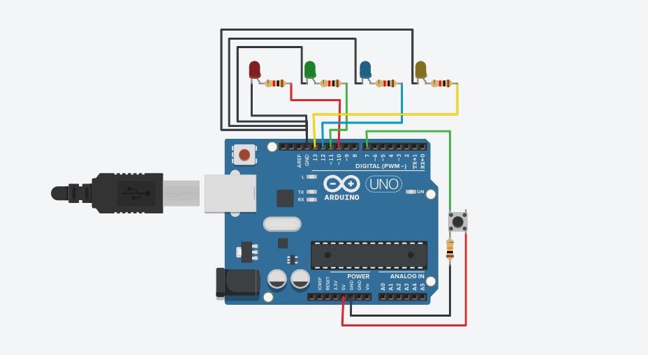
  // The press of button changes the pattern of LED glow

  const int ledPins[] = {10, 11, 12, 13};
  const int buttonPin = 7;

  int currentPattern = 0;
  int lastButtonState = 0; // For button state check

  void setup() {
    for (int i = 0; i < 4; i++) {
          pinMode(ledPins[i], OUTPUT);
    }
      pinMode(buttonPin, INPUT);
  }

  void loop() {
      int buttonState = digitalRead(buttonPin);

    if (buttonState == HIGH && lastButtonState == LOW) {
          currentPattern = (currentPattern + 1) % 4;
          delay(300); // debounce
    }
      lastButtonState = buttonState;

      runPattern(currentPattern);
  }

  void runPattern(int p) {
    switch (p) {
          case 0:
            // Pattern 1: Forward running light
      for (int i = 0; i < 4; i++) {
                clearLEDs();
                digitalWrite(ledPins[i], HIGH);
                delay(150);
      }
            break;

          case 1:
            // Pattern 2: Forward + Backward running light
      for (int i = 0; i < 4; i++) {
                clearLEDs();
                digitalWrite(ledPins[i], HIGH);
                delay(150);
      }
      for (int i = 2; i >= 1; i--) {
                clearLEDs();
                digitalWrite(ledPins[i], HIGH);
                delay(150);
      }
            break;

          case 2:
            // Pattern 3: Outside to Inside
            clearLEDs();
            digitalWrite(ledPins[0], HIGH);
            digitalWrite(ledPins[3], HIGH);
            delay(200);
            clearLEDs();
            digitalWrite(ledPins[1], HIGH);
            digitalWrite(ledPins[2], HIGH);
            delay(200);
            break;

          case 3:
            // Pattern 4: Quick strobe effect
      for (int j = 0; j < 10; j++) { // blink 10 times
                setAllLEDs(HIGH);
                delay(600);
                setAllLEDs(LOW);
                delay(600);
      }
            break;
    }
  }

  void clearLEDs() {
    for (int i = 0; i < 4; i++) {
          digitalWrite(ledPins[i], LOW);
    }
  }

  void setAllLEDs(int state) {
    for (int i = 0; i < 4; i++) {
          digitalWrite(ledPins[i], state);
    }
  }
▶️
Watch Now on YouTube
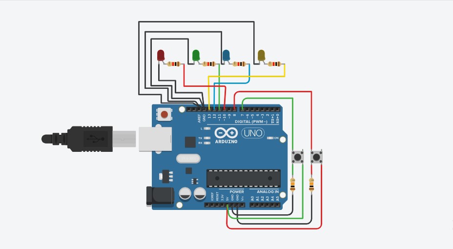
  // LED Control using Increment and Decrement Buttons
  const int ledPins[] = {10, 11, 12, 13};
  const int plushBtn = 7;
  const int minusBtn = 8;

  int ledIndex = 0;
  bool plushBtnState = HIGH;
  bool minusBtnState = HIGH;

  void setup() {
    for (int i = 0; i < 4; i++) {
          pinMode(ledPins[i], OUTPUT);
          digitalWrite(ledPins[i], LOW);
    }
      pinMode(plushBtn, INPUT);
      pinMode(minusBtn, INPUT);
  }

  void loop() {
      bool currentInc = digitalRead(plushBtn);
      bool currentDec = digitalRead(minusBtn);

      // Increment button pressed
    if (plushBtnState == HIGH && currentInc == LOW) {
      if (ledIndex < 4) {
              digitalWrite(ledPins[ledIndex], HIGH);
              ledIndex++;
      }
          delay(200);
    }

      // Decrement button pressed
    if (minusBtnState == HIGH && currentDec == LOW) {
      if (ledIndex > 0) {
              ledIndex--;
              digitalWrite(ledPins[ledIndex], LOW);
      }
          delay(200);
    }

      plushBtnState = currentInc;
      minusBtnState = currentDec;
  }
▶️
Watch Now on YouTube
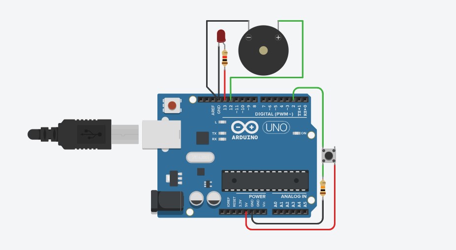
  // Buzzer gives beep for 100ms and LED status is toggled

  int ledState = LOW;
  int buttonState = 0;
  int lastButtonState = LOW;

  void setup() {
      pinMode(2, INPUT);
      pinMode(12, OUTPUT);
      pinMode(13, OUTPUT);
  }

  void loop() {
      buttonState = digitalRead(2);

    if (buttonState == HIGH && lastButtonState == LOW) {
          ledState = !ledState;
          digitalWrite(13, ledState);
          digitalWrite(12, HIGH);
          delay(100);
          digitalWrite(12, LOW);
    }
      lastButtonState = buttonState;
      delay(100);
  }
▶️
Watch Now on YouTube
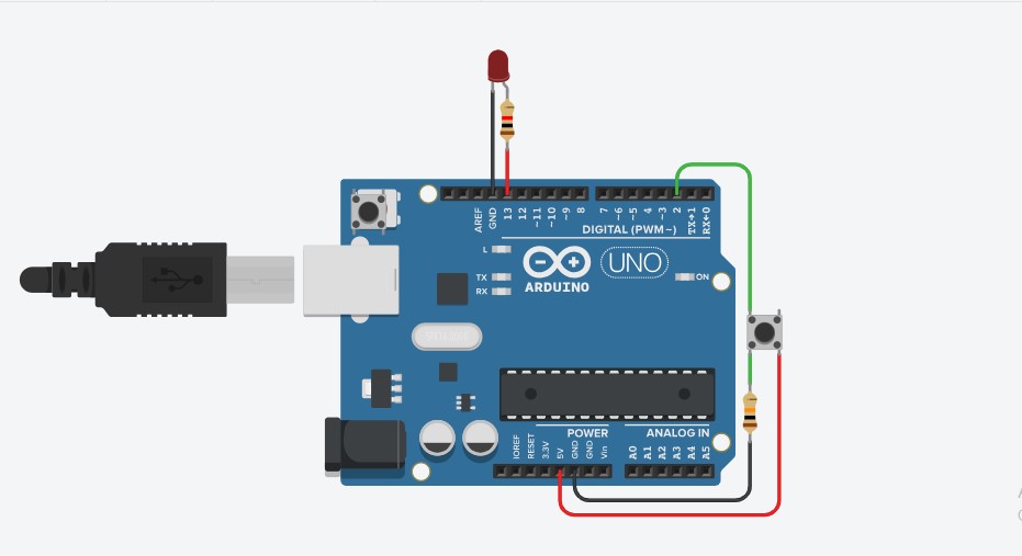
  // LED blinks/glow when button is pressed

  int buttonState = 0;

  void setup() {
      pinMode(2, INPUT);
      pinMode(13, OUTPUT);
  }

  void loop() {
      buttonState = digitalRead(2);
    if (buttonState == HIGH) {
          digitalWrite(13, HIGH);
    } else {
          digitalWrite(13, LOW);
    }
      delay(100);
  }
▶️
Watch Now on YouTube
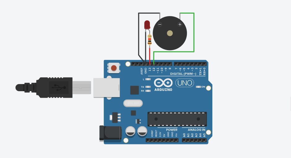
  // LED and Buzzer is on and off delay of 1 sec

  void setup() {
      pinMode(13, OUTPUT);
      pinMode(12, OUTPUT);
  }

  void loop() {
      digitalWrite(13, HIGH);
      digitalWrite(12, HIGH);
      delay(1000);

      digitalWrite(13, LOW);
      digitalWrite(12, LOW);
      delay(1000);
  }
▶️
Watch Now on YouTube
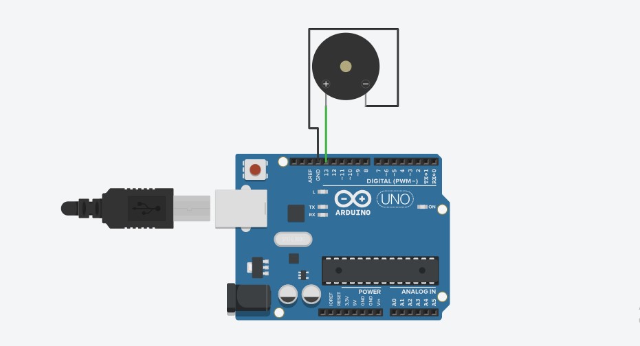
  // Buzz on/off with the delay of 1sec

  void setup()
  {
      pinMode(13, OUTPUT);
  }

  void loop()
  {
      digitalWrite(13, HIGH);
      delay(1000);
      digitalWrite(13, LOW);
      delay(1000);
  }
▶️
Watch Now on YouTube
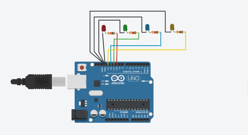
  int leds[] = {10, 11, 12, 13};

  // Each row represents a step in the pattern
  int pattern[][4] = {
    {1, 0, 0, 0},
    {0, 1, 0, 0},
    {0, 0, 1, 0},
    {0, 0, 0, 1},
    {1, 1, 0, 0},
    {0, 1, 1, 0},
    {0, 0, 1, 1}
  };

  int steps = sizeof(pattern) / sizeof(pattern[0]);

  void setup() {
    for (int i = 0; i < 4; i++) {
          pinMode(leds[i], OUTPUT);
    }
  }

  void loop() {
    for (int i = 0; i < steps; i++) {
      for (int j = 0; j < 4; j++) {
              digitalWrite(leds[j], pattern[i][j]);
      }
          delay(3000);
    }
  }
▶️
Watch Now on YouTube
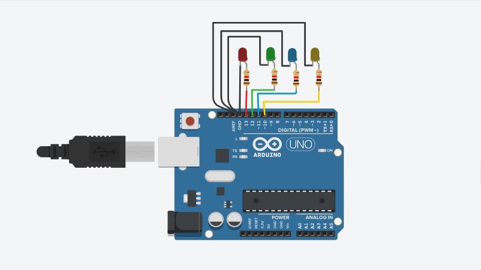
  // Blinks 4 LEDs one-by-one

  void setup() {
    for (int i = 10; i <= 13; i++) {
          pinMode(i, OUTPUT);
    }
  }

  void loop() {
    for (int i = 10; i <= 13; i++) {
          // Turn OFF all LEDs
      for (int j = 10; j <= 13; j++) {
              digitalWrite(j, LOW);
      }
          // Turn ON current LED
          digitalWrite(i, HIGH);
          delay(1000);
    }
  }
▶️
Watch Now on YouTube
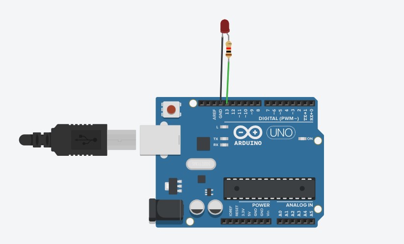
  // LED Blink with 2 Second Delay

  void setup() {
    // Pin 13 ko output mode me set karna
    pinMode(13, OUTPUT);
  }

  void loop() {
    // LED ON karna
    digitalWrite(13, HIGH);
    delay(2000); // 2 second delay

    // LED OFF karna
    digitalWrite(13, LOW);
    delay(2000); // 2 second delay
  }
▶️
Watch Now on YouTube